1. Maximized User Convenience
Communication Module
- RS-485 Capability is built-in
- Modbus-RTU, Metasys N2
- BACnet MS/TP is embedded as standard
- LonWorks option can be added
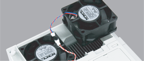
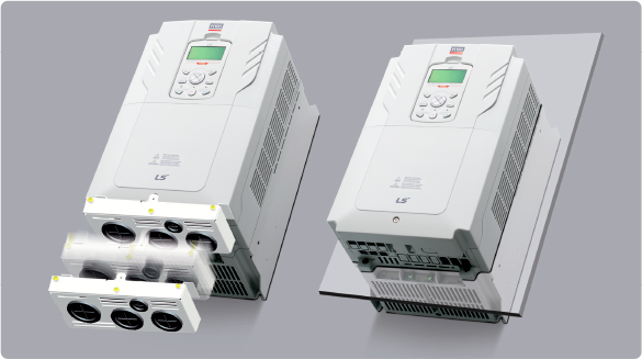
Easy to Change Cooling Fan
It is easy to change the cooling fan
without opening the cover of the drive
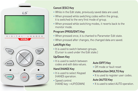
Keypad Exclusive for HVAC
Used to issue commands, configure drive parameters, and for monitoring drive status
- HAND mode (Local, Control, Mode) or AUTO Mode (Remote Control Mode) may be selected.
- HAND Mode: Used when selecting frequency or run/stop commands.
- AUTO Mode: Drive operated using the keypad. Multifunctional terminal block and communications.
- Fault Status Monitoring
Specification Level Option (Conduit Kit)
Acquired UL open type & enclosed type 1 certification
- When the conduit option is used, the drive meets UL Enclosed Type 1 specifications
Flange Type
If the space is too small, a heat sink can be installed outside the panel
DC Reactor
A built-in DC reactor to improve power factors and reduce THD is installed.
- DC Reactor built-in as a standard for 400V 37-90kW
Built-in EMC Filter
A built-in EMC filter to respond to the specifications for noise reduction
- 400V 0.75~30kW Built-in as default (C3)
- 400V 37~55kW Built-in option can be selected (C3)
※ 75~90kW satisfies EMC specifications even without a filter
Compliant with Global Specifications
UL Plenum Rated
(American standards for conditional fire safety)
※ Suitable for installation in compartments handing conditioned air
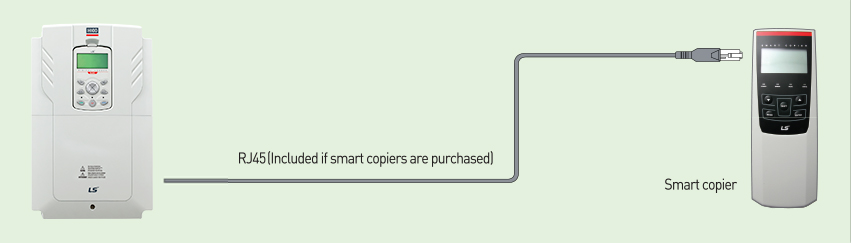
Smart Copier
- Power-free Operation
- LED Feedback
- Parameters Read/Write
- Easy to Install
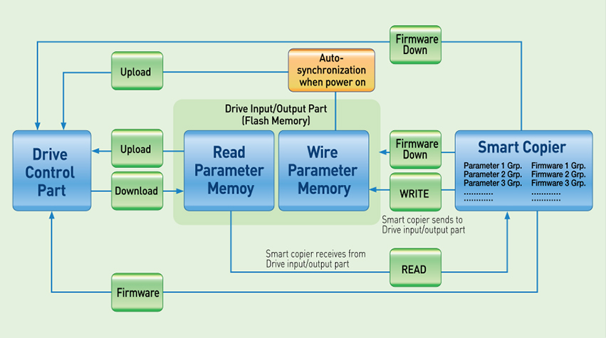
Data Flow in Smart Copier
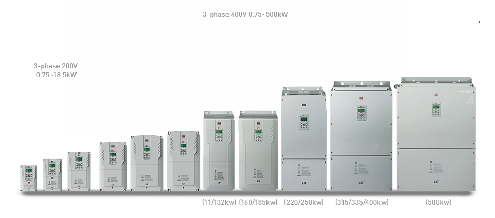
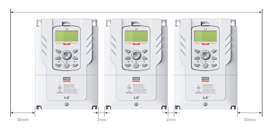
2. Efficient Use of Space
Side-by-Side Installation
The size of the control board is significantly reduced when multiple drives are installed by minimizing the distance between products installed
※Side-by-side installation is unavailable for 37~90kW
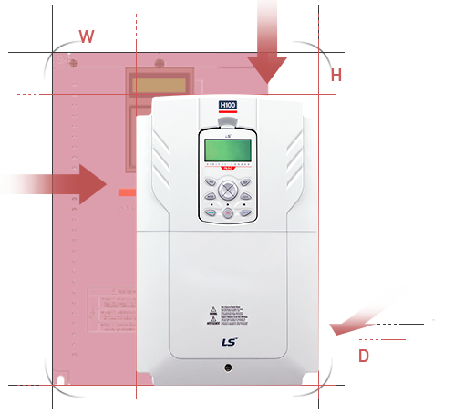
Reduced Size
Main components are optimally deployed through thermal radiation analysis and 3D design to reduce size by 34% compared to iP5A (Volume based)
3. Stable System Control
LSLV-H100 drives are intelligent drives equipped with various protective and operation functions for continuous stable operation in response to external environmental changes.
Soft Fill Operation
Prevents pump damage caused by extreme pressure change during initial operation of pumps or inside pumps.
Start Ramp & End Ramp
Prevents pump damage by changing ramps using the acceleration/deceleration time setting upon initial pump operation
Dec Valve Ramp
Prevents pump and pipe damage caused by sudden pressure changes when pumps are stopped or a pump valve is closed, Deceleration time may be set.
Multi Motor Control
MMC is used when a single drive is used to control multiple motors in the pump system.
It can control 1 main motor and 5 auxiliary motors.
Scheduling (Time Event: Real Time Clock)
Prevents pump damages caused by dramatic pressure changes during initial operation or pumps or inside pumps.
Flow Compensation
Compensates for hydraulic loss that occurs when the length of pipes are too long, adding a compensation rate depending on the inverter output frequency.
Energy-saving Display (Payback Counter)
Commercial energy consumption is compared to the amount of energy used by the drive to calculate the amount of energy saved.
Power-on Resume
When the drive restarts after it was stopped due to power interruption upon communication control, 'Power-on Resume' is used to follow the previous control command.
Sleep, Sleep Boost, Wake-up
It is used to put the drive on standby and restarts it using the amount of energy used by the drive to calculate the amount of energy saved.
Auto Torque Boost
The drive outputs voltage for the drive by controlling the level of boost to fit the load by itself.
Lubrication Control
When a control command is made in the Flow/Oiling Systems, lubrication signals are output for a certain period before the motors are started. Drive control immediately begins form the signal output point until the signals are turned off after the set time
Damper Control
When a damper exists in the system configuration, the drive will command the damper to open/close or receive feedback signals for protection.
Detection of Pipe Broken
Upon PID operation, pipe damages or leakage is detected to display a warning or a trip.
Level Detection
When the drive is operated under a frequency that is beyond the set frequency and source (voltage, current, and etc.) values to be detected are above or below the user set values, it generates a trip or activates a relay for protective operation
Pre-Heat
Pre-heats motors by direct current output when the motors are at fixed state of time in order to prevent condensation in the motors
Under Load Protection
When running pumps including no flow and dry pumps under the set frequency, the drive issues a warning function and when the trip is generated, free-run, deceleration, or stop can be selected.
Macro Setting
If a particular application is selected, frequently used parameters and set values are changed and registered in a macro group.
KEB, Kinetic Energy Buffering
Upon loss or momentary interruption of input power, if the KEB is set, the drive maintains a DC Link Voltage using regenerated energy from the motor during the interruption period.
Pump Clean
Upon pump operation, the efficiency of pumps may decline when foreign substances are stuck in an impeller. The pump clean removes foreign substances to extend pump life.
Aux Motor PID Compensation
Pipe flow increases and conduit pressure decreases as the number of auxiliary motors increases. The 'Aux Motor PID Compensation' is used to compensate pressure loss suitable for the given motor when operating auxiliary motors.
Load Tuning
Establishes load (current & power) curves based on drive frequency so as to make load characteristics curve required for 'Under Load' and 'Pump Clean.'
Fire Mode
When an emergency such as fire occurs at the suction/exhaust fans, but hardware did not fail nor has a critical defect, the drive is continuously operates to protect other systems under the set frequency and direction.
Frame Design